



Mini Excavator for Pipeline and Cable Laying — Trench Precision That Pays
Pipeline and cable installation is one of the most specification-sensitive tasks a mini excavator performs. On a digging job, dimensional variation costs little — the hole is big enough or it is not. On a pipe laying job, every centimetre of excess trench width is backfill material you are buying, compacting, and paying to have tested. On a cable conduit job, every centimetre of excess depth is extra excavation time on every metre of run. The machine that controls trench dimensions precisely reduces material cost and time on every linear metre of the job.
This article covers bucket selection, trench geometry management, bedding preparation, and the machine class decisions that make pipe and cable trench work efficient.
Bucket Width — The First and Most Important Decision
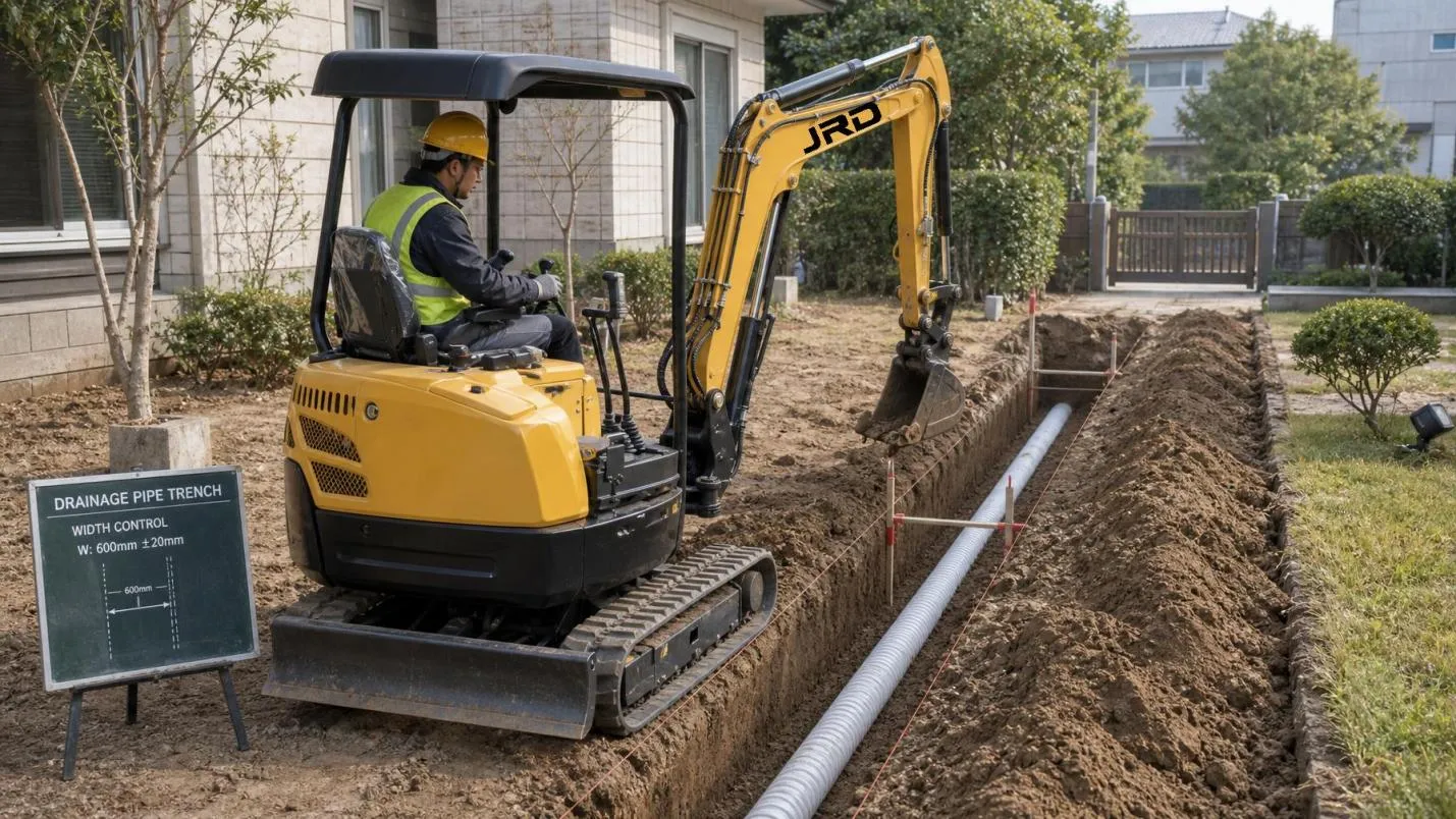
On pipeline and cable work, bucket width should match the trench specification, not the machine class default. Most machines ship with a general-purpose digging bucket that is wider than the minimum required trench for standard pipe diameters. Running a 400 mm bucket on a trench specified for a 150 mm pipe wastes 200+ mm of width on every linear metre.
Standard trench width requirements (pipe OD + working clearance):
100–150 mm diameter pipe: minimum trench width typically 300–350 mm — a 300 mm bucket is correct
200–250 mm diameter pipe: minimum trench width typically 400–450 mm — a 400 mm bucket is correct
300–375 mm diameter pipe: minimum trench width typically 500–600 mm — a 500 mm bucket is correct
Cable and conduit (25–100 mm diameter): minimum trench width 200–250 mm — a 200–250 mm narrow bucket is correct, and significantly faster per linear metre than a wider bucket that must be refilled
The 10 series to 17 series machines handle the full range of residential and light commercial pipe diameters with appropriate bucket selection. The 06 series machines are limited to narrow bucket work — cable conduit, irrigation lines, and small-bore drainage — due to their breakout force and limited dig depth.
Trench Depth Management
Most utility installation specifications require the trench bottom to be within ±25 mm of design depth. Exceeding this on either side has consequences: too shallow means the pipe or cable is inadequately covered; too deep means over-excavation that requires bedding material to reinstate the design invert level.
Set the bucket curl reference: establish a consistent bucket curl angle that puts the cutting edge at the target depth when the boom is in the mid-reach position. Maintain this angle throughout the run
Use a depth gauge: a simple rod gauge set to the design depth and checked every 10–15 m of trench run catches drift before it compounds. More sophisticated operations use a laser grade receiver on the stick for continuous depth feedback
Work in consistent passes: two-pass digging (initial rough cut, then cleanup to grade) produces more consistent floors than single-pass deep cuts in one attempt
Avoid over-digging on transitions: at bends, tees, and entry/exit points, the instinct to clear more space results in over-depth that requires remediation. Mark these points on the ground and reduce dig speed through them
Trench Wall Control
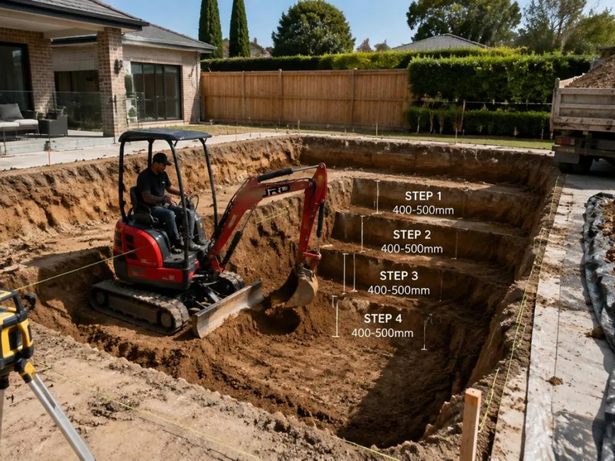
The trench wall condition affects both backfill cost and pipe safety. In cohesive soils (clay, firm silt), vertical walls are achievable. In granular soils (sand, gravel), walls require battering or shoring at depth.
On residential pipeline work, most trenches stay within 1.2 m depth — the threshold below which formal shoring is required in most markets. For work up to this depth in stable soil:
Cut walls in a single straight pass: using the same vertical bucket position for each side of the trench produces parallel walls. Angling the bucket into the cut on each pass creates tapered walls that waste width at the bottom
Do not allow workers into the trench during machine operation: even stable-looking walls at 900–1,000 mm depth can collapse without warning if vibration, saturation, or adjacent load is applied
Trim loose material from the wall face: hanging loose material from the wall face will fall during bedding and pipe laying operations, contaminating the bedding layer
Pipe Trench Bedding — Getting the Floor Right
The trench floor condition determines whether the pipe sits at the correct invert level and whether differential settlement occurs. Most pipe laying specifications require a granular bedding layer (typically 100–150 mm of pea gravel or sand) placed and levelled before the pipe is set.
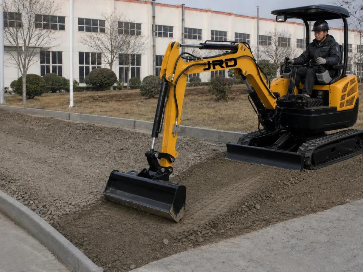
A mini excavator can prepare a consistent bedding surface with a flat-edge grading bucket:
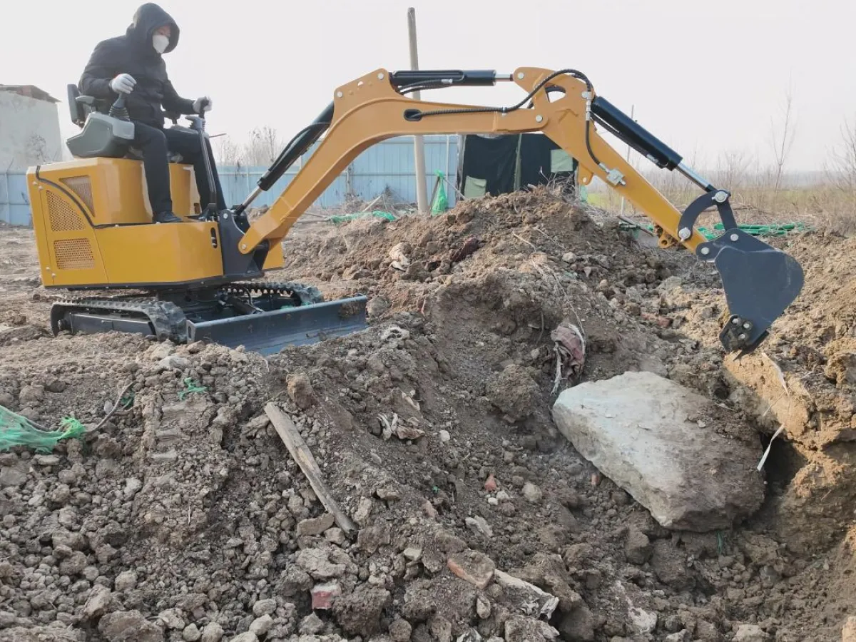
Remove all large material from the trench floor: even a single stone larger than 50 mm under a rigid pipe can cause a point-load failure over time. The grading bucket flat edge drags loose material out efficiently
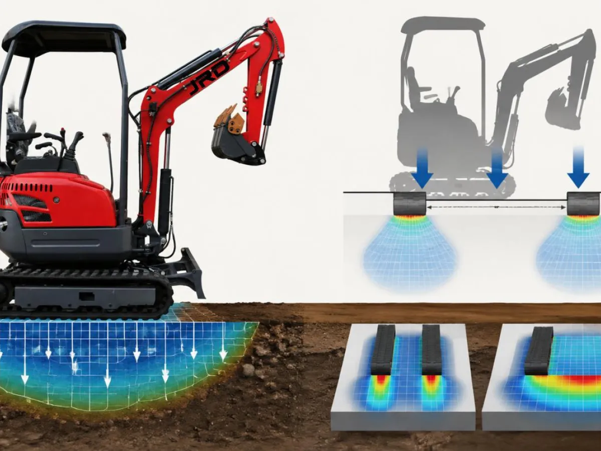
Compact the floor subgrade: the bucket base can be used as a light tamper on the trench floor before bedding is placed — this is not a substitute for mechanical compaction but reduces the risk of post-installation settlement in soft ground
Level the bedding layer after placement: dump bedding material, then drag the flat bucket back through the trench at the correct invert level to distribute and level the bedding in a single pass
Lowering Pipe Into the Trench
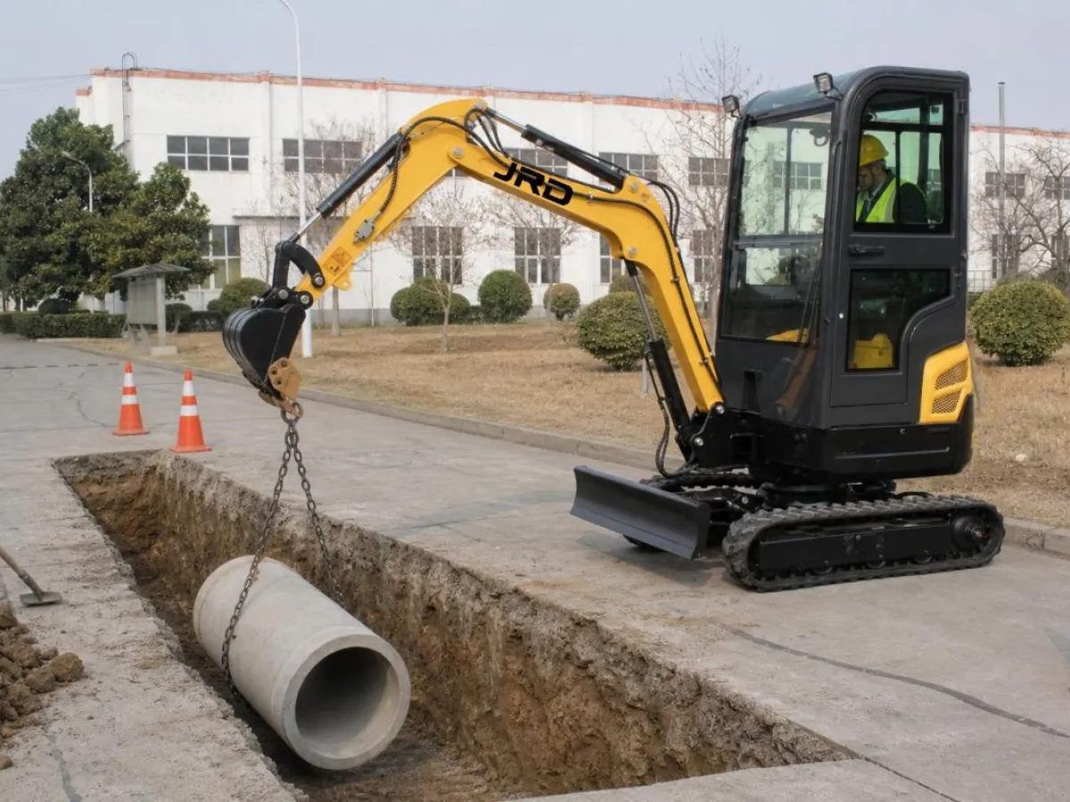
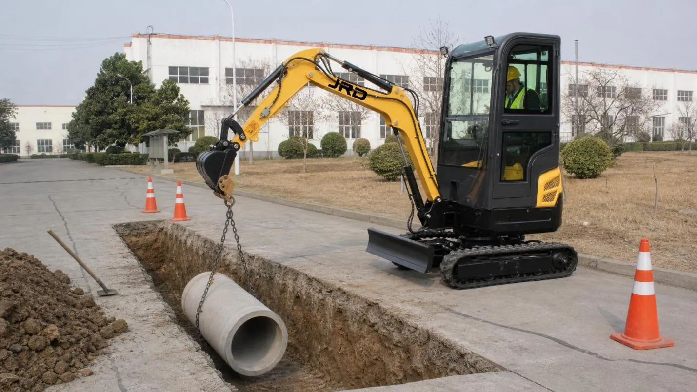
A mini excavator can lower pipe sections into the trench as well as dig it. For pipes up to 300 mm diameter, a sling around the pipe barrel and a hook or bucket pin provides the lift point. For larger diameter sections, a dedicated pipe lifter or headboard attachment gives better control.
A hydraulic thumb is a significant advantage when lowering pipe — the operator can grip the pipe barrel and control its angle during lowering, keeping the spigot aligned with the socket of the previously placed section without a second person in the trench to guide it. On longer pipe runs, this reduces the crew size required by one and keeps workers out of the trench during machine operation.
Approach the trench edge slowly and with the pipe at minimal height — do not swing with a pipe load extended at full boom height
Lower to 200–300 mm above the bedding before lateral positioning — this reduces the arc of movement required for alignment
Do not drop: lower pipe sections onto the bedding without impact — a dropped concrete pipe section can crack; a dropped HDPE section can deform out of round, making joint assembly difficult
Backfill and Compaction
After pipe installation, the backfill technique determines long-term trench stability. For road crossings or paved surfaces, inadequate compaction causes settlement that eventually shows as a depression over the trench line. For garden and soft-surface trenches, settlement is less critical but still affects the visual result.
A mini excavator handles initial backfill placement but cannot achieve the compaction density required by most civil specifications. A compaction plate attachment on the auxiliary hydraulic circuit provides mechanical compaction in the trench in lifts — typically 200–300 mm uncompacted layer thickness per pass. Alternatively, a hand-operated plate compactor alongside the machine compacts each lift before the next is placed.
For cable and conduit trenches in landscaped areas, the machine can backfill in a single operation since compaction to structural density is not required — the goal is to return the surface to close to original level without voids that will cause depression over time.
Machine Classes for Pipe and Cable Work
For residential cable conduit and irrigation line work: 06 series to 12 series machines with 200–300 mm narrow buckets. These machines keep ground disturbance to a minimum and are fast on light, shallow trenches.
For drainage and stormwater pipe (100–300 mm diameter) in residential and light commercial: 12 series to 17 series machines with 300–400 mm buckets. These classes combine adequate dig depth (1.8–2.3 m) with bucket force sufficient for compact subsoil at depth.
For pressurised main water and gas lines at greater depth: 17 series to 22 series machines where dig depth requirements exceed 2.5 m and soil conditions may include rock or compacted fill. At these depths, a variable piston pump — as on the 17 series — provides better control of bucket speed and force as depth increases and the boom geometry puts more load on the hydraulic circuit.
Conclusion
Pipeline and cable laying is the application where bucket width selection and trench depth discipline have the most direct impact on job cost. Every millimetre of excess width is fill material; every centimetre of depth error is either remediation cost or specification non-compliance. The mini excavator that is set up correctly for the pipe diameter — right bucket, right depth reference, and flat-edge bucket for bedding — completes pipe runs faster than manual methods and within the dimensional tolerance that specification requires.
Match the machine class to the pipe diameter range, specify the bucket width to the trench requirement, and use a hydraulic thumb if pipe lowering is part of the scope. These three decisions determine most of the productivity outcome on pipeline work.
Need a compact excavator that works corners, walls, and confined zones without constant repositioning?
JRD Machinery offers CE-certified mini excavators with boom lateral swing on the 16, 22, and 25 series — including telescopic chassis and pilot control options for professional site work.
Visit www.jrdmachinery.com to compare specifications, or contact us for a model recommendation based on your specific site requirements and export destination.
Email: info@jrdmachinery.com
Whatsapp: +86 136 9536 6564
Website: www.jrdmachinery.com