



Mini Excavator for Utility Installation — Trenching, Depth, and Pipe Laying Technique
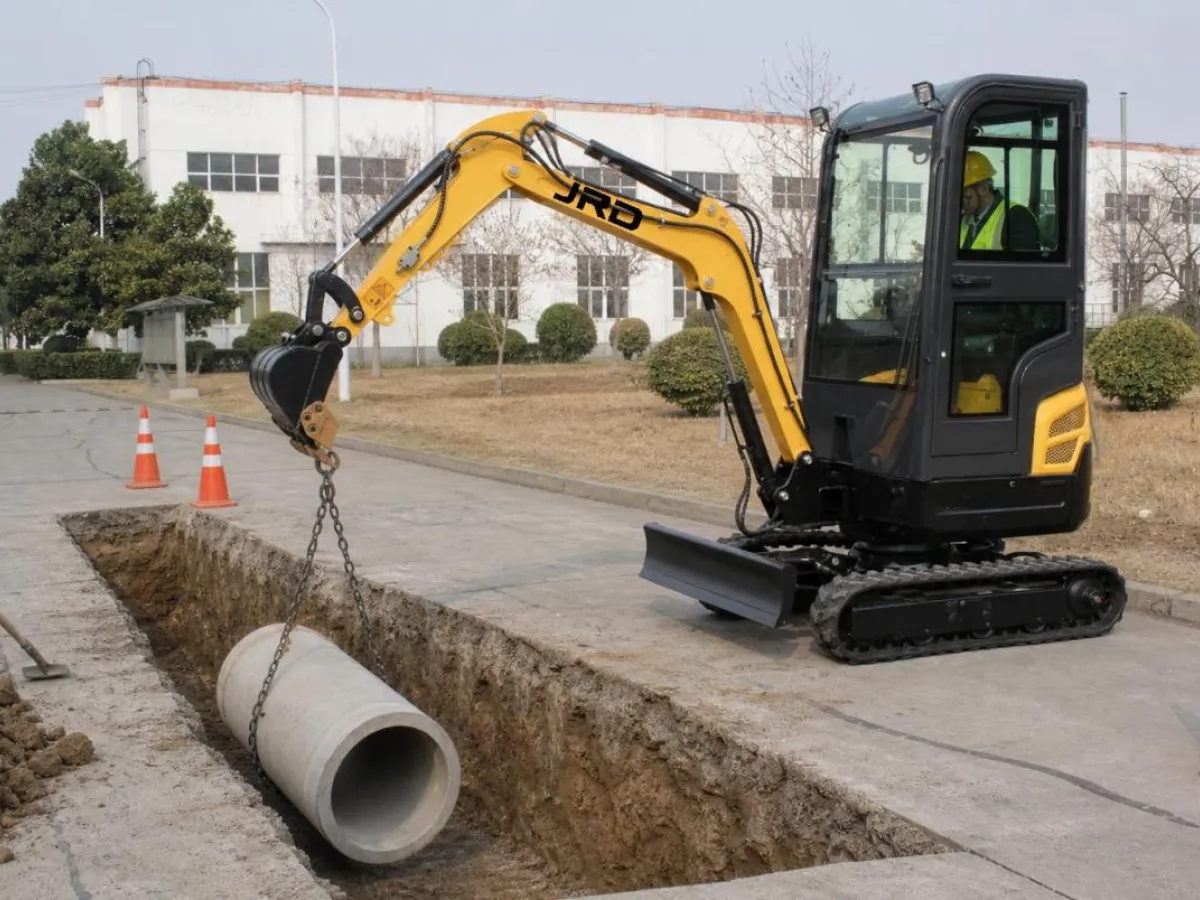
Utility installation work — water mains, drainage pipe, electrical cable duct, gas service connections — represents one of the largest volume applications for compact excavators globally. The trench dimensions are prescribed by the utility specification, the depth is fixed by the service invert requirement, and the work is often done in public streets or established gardens where surface damage is both visible and expensive. Mini excavator trenching in this context is not just about moving material; it is about moving exactly the right material to exactly the right dimension while minimising disturbance to everything adjacent to the trench line.
This article covers how to match machine and bucket specification to the trench requirement, how to achieve consistent invert level accuracy without laser grade equipment, the technique for clean trench walls in different soil types, and how backfilling and compaction around pipe or duct is managed with the same machine that dug the trench.
Matching Bucket Width to Trench Specification
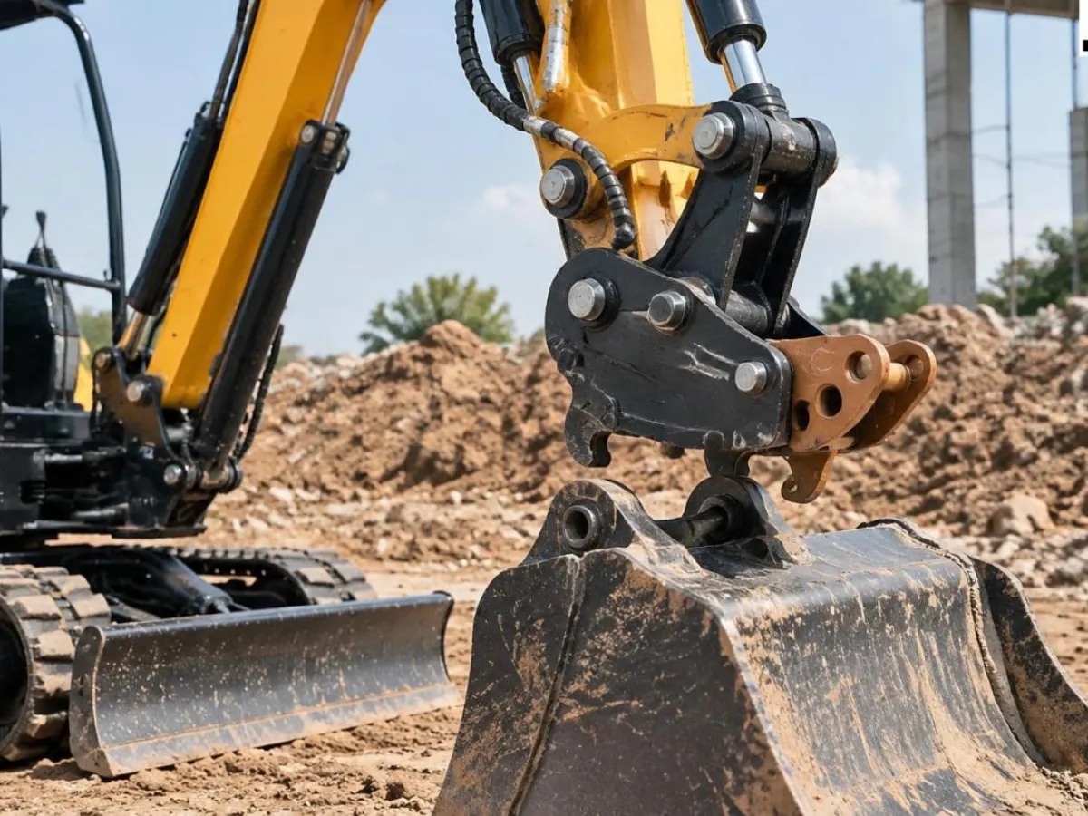
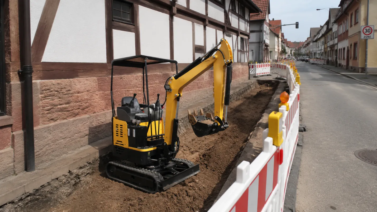
Utility trench specifications are written around the pipe or duct outer diameter plus the minimum bedding sand or granular material clearance on each side. A 100 mm diameter water service pipe requires a minimum trench width of typically 300 mm to allow 100 mm of bedding on each side of the pipe — the 200 mm digging bucket is the correct tool for this profile, cutting a trench that is slightly wider than the bucket itself due to soil disturbance at the cut face.
The 400 mm bucket — the standard digging bucket in the range — is appropriate for 150 to 200 mm diameter pipe in the same bedding configuration, or for cable duct runs where multiple conduits are installed in the same trench. The wider bucket moves more material per pass, which is productive for longer trench runs in consistent soil, but produces more spoil volume that must be managed and backfilled — a consideration in urban sites where spoil storage space is limited.
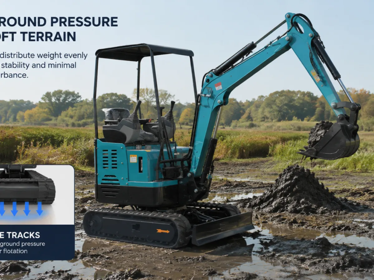
The mud bucket (wide, flat profile, no teeth) is the correct choice for mini excavator trenching in soft or wet ground where the toothed bucket churns rather than cuts the material cleanly. Water main installation in saturated clay — a common scenario in road-based utility work — benefits from the mud bucket's flat base, which cuts a clean trench floor at the design invert depth rather than the ragged profile that toothed buckets leave in soft material.
Trench Depth and Machine Reach — Matching the Right Model to the Utility Specification
The maximum digging depth of a compact excavator is the limiting factor when the utility specification calls for deep service installation. Frost-depth water mains in cold climates may need to be installed at 1.2 to 1.5 metres below finished surface; gas mains may require 0.75 to 1.0 metres; electrical high-voltage cable installations may specify 0.9 metres minimum.
The 06 series at 1,091 mm maximum digging depth covers shallow cable and drainage applications but cannot reliably achieve the 1.2 m depth required for frost-protected water mains in many cold-climate specifications. The 10 series at 1,736 mm and the 12K at 1,650 mm cover the majority of residential utility installation depth requirements across most climate zones. The 13K at 1,740 mm adds digging force for harder soils at the same depth range. For installations deeper than 1.8 metres — industrial gas or water main replacement, for example — the 17 series at up to approximately 2,150 mm maximum depth provides adequate reach for all but the deepest residential utility specifications.
Maximum digging depth figures assume the machine is working on the surface level with the trench — once the machine drops a track into the trench edge or works from a sloped approach, the effective working depth changes. In practice, allow 10 to 15% less than the rated maximum depth as the design working depth for consistent production, reserving the rated maximum for spot corrections where the invert needs to be deepened.
Achieving Accurate Invert Level Without Laser Equipment
Professional utility trenching requires the trench floor (the invert) to be at a consistent specified depth across the entire run, with any gradient change made deliberately rather than randomly. Laser grade control equipment — a laser transmitter and receiver mounted on the machine — provides automated invert control on machines set up for it, but it is not standard on compact excavators in this class. Consistent invert accuracy without laser equipment requires technique.
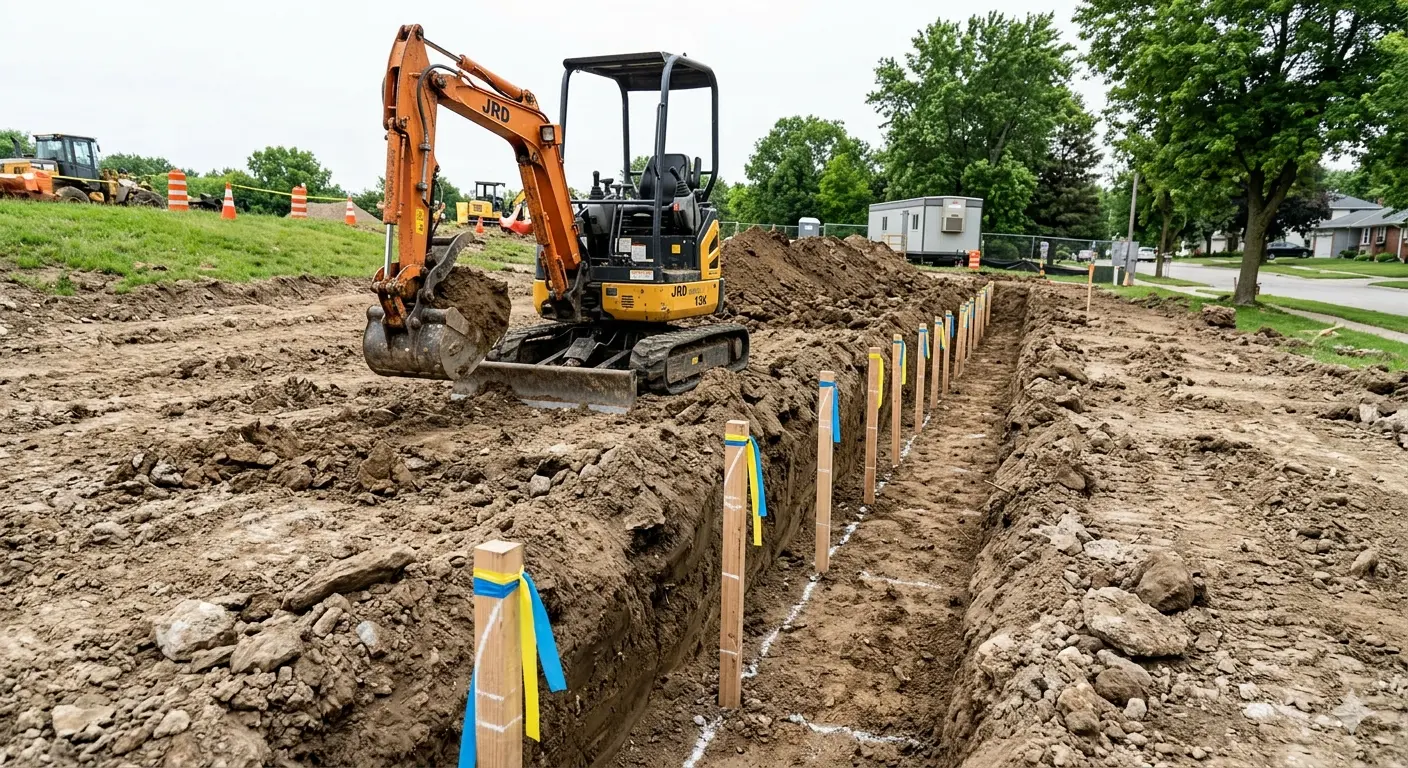
The most reliable low-tech method for consistent mini excavator trenching depth: cut a depth stake at the trench start point, marking the design invert depth on a timber stake driven into the trench floor at the starting point. Use a level and tape to set subsequent stakes at the design gradient along the trench line at 5-metre intervals. The operator uses these stakes as reference targets, checking bucket position against each stake as the trench progresses. An experienced operator working with correctly set grade stakes can hold invert to within ±20 mm over a 50-metre run — adequate for drainage design tolerances and acceptable for most service pipe specifications.
For applications where the gradient is critical — drainage trenches where the pipe must maintain a minimum fall to prevent silt accumulation — the laser level approach is worth the additional equipment cost. The productivity gain from not needing to correct low spots after the initial dig pass pays back the equipment rental cost quickly on runs longer than 30 metres.
Clean Trench Walls — Technique Differences by Soil Type
The objective of clean trench walls is not aesthetic — it is structural. A trench with crumbled or overcut walls requires more bedding material to fill the voids around the pipe, and the irregular wall surface does not compact predictably during backfill, creating settlement risk in paved surfaces above the trench line. Clean walls start with the right bucket and the right crowd technique.
In firm clay and compacted soil, a standard toothed bucket cuts clean vertical walls with a direct crowd motion — pushing the bucket straight down and then crowding the stick to bring the bucket through the bottom of the cut. The teeth break the material at the cut face and the bucket sides shear the wall cleanly. In this soil type, the main risk to wall quality is running the bucket too fast through the cut — slow, deliberate crowd strokes produce cleaner walls than fast passes.
In sandy or loose soil, the trench walls want to slump as soon as the support from the adjacent soil is removed. The technique response here is to work in short sections — no more than 2 to 3 metres of open trench at a time — and install the pipe and begin backfill before moving to the next section. Attempting to dig the full trench run and then lay pipe is a recipe for wall collapse and spoil contamination of the trench floor in sandy ground. If the utility specification requires the full trench run to be open simultaneously (for inspection, for example), trench box shoring is required, which is a separate equipment requirement.
Backfilling and Compaction — Completing the Job Without Damaging the Work
The backfill sequence for utility trenches is as specified by the pipe manufacturer and the utility authority — typically a granular bedding layer around the pipe, a selected granular surround to 150 mm above the pipe crown, and then either compacted native spoil or imported granular material to the surface reinstatement level. The compact excavator manages the first two layers by controlled bucket tipping of the bedding material directly over the pipe — not by dragging material into the trench with the bucket curling against the pipe.
Compaction of the surround material to the density specified by the utility authority is done in layers — typically 150 mm loose depth compacted to 100 mm. A vibrating plate compactor is the standard tool for this, operated in the trench after each layer is placed. The compact excavator cannot itself compact material within the trench — the machine weight acting through the bucket would damage the pipe at any realistic surround depth. This is the stage where most utility trenching projects require a second operative working in the trench while the machine operator continues digging the next section.
Surface reinstatement — replacing the road surface or paving above the backfilled trench — is the final quality test for the entire operation. A trench that settles after reinstatement is evidence of inadequate compaction at some layer in the backfill sequence. In paved surfaces, trench settlement produces a visible sag in the road surface that road authorities will require to be corrected at the contractor's cost. The compact excavator's role in preventing this is indirect: clean trench walls that don't slump during backfill, accurate invert depth that allows the correct pipe depth and bedding thickness, and careful bucket placement of the initial backfill layers rather than dropping material from height.
Specifying compact excavators for utility trenching, service connection, or drainage installation work?
JRD Machinery offers CE-certified mini excavators with narrow trenching bucket options, pilot control for invert accuracy, and boom swing configurations for trench work along walls and kerb lines.
Visit www.jrdmachinery.com to compare model trench depth specifications, or contact us for a trenching-application equipment recommendation based on your pipe size and maximum depth requirement.